
- MAX7219 LED DISPLAY PROTEUS LIBRARY SERIAL
- MAX7219 LED DISPLAY PROTEUS LIBRARY DRIVER
- MAX7219 LED DISPLAY PROTEUS LIBRARY CODE
3 Controlling the LED Matrixes with an Integrated Circuit(IC): MAX7219Įverybody is familiar with LED Matrixes. This will return true after each scroll is completed then the displayReset() function will be called to reset the display. Inside the loop() function, we will use an if statement with the displayAnimate() function that will start the scrolling of the text. Display.displayScroll("SCROLL", PA_RIGHT, PA_SCROLL_LEFT, 150) loop() The higher the value the slower will be the movement of the text. Lastly, the fourth parameter is the time in milliseconds between the text frames. We have set it to ‘PA_SCROLL_LEFT’ that means the text will scroll towards the left side. The third argument is the direction of the scroll. In our case the text is ‘SCROLL.’ The second parameter is the alignment of the text in case of a delay. The first parameter is the text that you want to scroll. Inside the setup() function, after initializing the LED matrix, setting its brightness and clearing the display we will the displayScroll() function to set up the scrolling action. As we are using FC16 model thus it consists of four 8×8 LED arrays. Thirdly, we will define the maximum number of ICs in our LED matrix. #define HARDWARE_TYPE MD_MAX72XX::GENERIC_H Defining number of MAX7219 ICs If you are using the generic model instead of FC16 then uncomment the second line and comment the line where we are defining FC_16HW. Secondly, it is very important to define the correct type of MAX7219 LED matrix that you are using. Moreover, we have included the MAX7219 module libraries that we previously installed for the proper functionality of the LED matrix. We are including SPI.h as we are using SPI communication protocol between the two device. Including Librariesįirstly, we will include all the necessary libraries for this project. MAX7219 LED DISPLAY PROTEUS LIBRARY CODE
In this part we will discuss how the code works. MD_Parola Display = MD_Parola(HARDWARE_TYPE, CS_PIN, MAX_DEVICES) #define HARDWARE_TYPE MD_MAX72XX::GENERIC_HW #define HARDWARE_TYPE MD_MAX72XX::FC16_HW Uncomment according to your hardware type MAX7219 LED Dot Matrix Module Interfacing with Arduino CLK: This is connected to the CLK pin of the next module.CS: This is connected to the CS pin of the next module.It is connected to DIN pin of the next module.
 GND: It is connected to the GND on the next module. VCC: It is connected to VCC (5V) on the next module. The output connections of the LED matrix are connected with the next module if there is a need to attach more units.
MAX7219 LED DISPLAY PROTEUS LIBRARY SERIAL
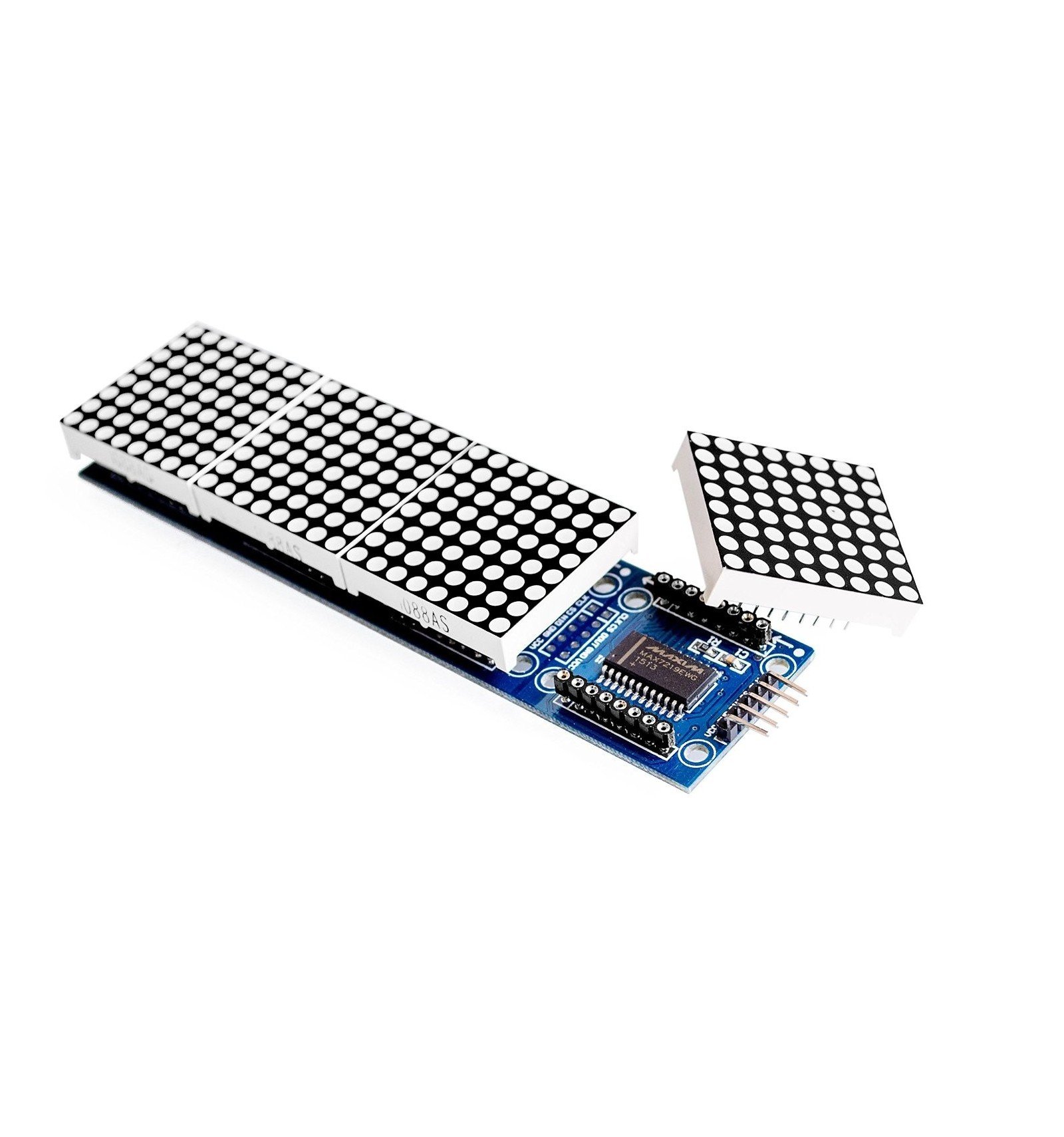
CLK: This is called the ‘Serial Clock’ pin which is used in SPI serial clock output. CS: This is the Chip Select pin for SPI communication. It is used as the SPI input to the module.  GND: This is the ground pin which should be connected with the ground pin of Arduino. It is connected with 5V pin of Arduino if the brightness is set to half value. VCC: This pin supplies power to the MAX7219 module. The input connections of the LED matrix are connected with the Arduino UNO. Pinout of MAX7219 LED Matrix Module Input Connections If the row gets positive voltage and the column gets negative then only a particular LED will glow. To Turn on a specific do, we need to apply a positive voltage to the respective row of that dot and negative or ground to the respective column of that dot. This method of controlling a large number of LEDs with few pins is known as multiplexing. Otherwise, we will need 64 pins to control an 8×8 LED matrix. By doing this, the required number of I/O pins has been reduced to 16. The reason for connecting all rows and columns together is to save the required number of pins to control each LED dot. Each LED is referred to as a dot.įor making an 8×8 dot matrix all the anodes terminals are connected together in rows R1 to R8, similarly, the cathodes are connected together in columns C1 to C8. Each LED is addressed by its row and column number. The typical 8×8 LED matrix is shown below which comprises of 64 LEDs, 8 for each row and column. LED dot matrices are available in various dimensions (7×5,8×8, 7×15, etc).
 MAX7219 LED DISPLAY PROTEUS LIBRARY DRIVER
MAX7219 8-Digit LED Display Driver LED Dot Matrix


 0 kommentar(er)
